The gearboxes used for the 249 cc MOV and the 349 cc civilian MAC and the MAF Services version were virtually identical. In fact they bore considerable resemblance to that of the GTP and also to the bigger models in the 'K' range. The clutch, the only item likely to puzzle the unacquainted with less conventional Veloce ideas, can be reconditioned from current Velocette spares. Its working is fully explained in instruction books for 1954 Velocette machines, obtainable from the company's factory at York Road, Hall Green, Birmingham, 28. Details of its maintenance and adjustment, which is critical, are set out in a later paragraph.
Special tools necessary include the maker's peg-type spanner, No. A61/2AS – referred to last week in connection with engine shock-absorber dismantling work – which is used to unscrew the clutch sleeve-gear nut. The chances are that most of this initial work will have been disposed of earlier, for it is a feature of the machine that, in removing the primary chain preparatory to taking the engine out of the frame, the clutch assembly must come down and the rear half of the chain case be taken off. Little more than a passing note on that work is called for now therefore.
Enjoy more The Classic MotorCycle Magazine reading every month.
Click here to subscribe & save.
To assist in replacing the sleeve-gear nut against clutch-spring pressure, Veloce recommend an adaptor, details of which are illustrated. It is possible that a private owner will wish to remove the steel ring which retains the gearbox sleeve-pinion ballrace. The ring is screwed into its location and a special extractor tool is required. Veloce list it as No. X2725 and details of dimensions are included here for the handyman who can make up his own gadgets.
Dismantling Procedure
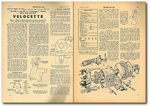
The gearbox end-cover carries a ball-type mainshaft bearing which can be jarred out after heating the surrounding metal, and also a big bush member carrying the kick-starter spindle which, itself, is hollow and acts as a housing for the loose layshaft bush. There is no impelling need to dismantle any of this mechanism if it is in good working order; the only reasons for taking these components apart are (1) a broken kickstart spring, (2) a damaged ratchet face, or (3) curiosity. Note from the little sketch the important part played by the hexagon-headed screw-peg which anchors the kickstart spring; the dotted extension to the spring indicates the degree to which it is 'wound up' when assembled, a process carried out with the ratchet member held stationary. Two small locating holes on the face of the ratchet can be engaged with improvised pegs – nails driven into a wood bench suffice – while the outer bush member is 'wound up' and the kickstart lever and cotter assembled. Take care not to lose the hardened-steel pad which takes layshaft end-thrust.
 The larger of the sketches shows the end-cover removed and the gears part-withdrawn, likewise, the camplate which, when assembled, goes inside the box, the recess marked by the little arrow being placed adjacent to a similarly-marked centre segment. It is wise, actually, to mark the cam-plate and centre piece before separating them, so that there is no doubt later on about their respective positions. It helps to note these details during the dismantling stage. Another little point is the use on Army-type MAF models of a 'Seeger' circlip at the kickstart end of the layshaft to retain the layshaft ratchet.
Slackness or 'roughness' in any of the three ball-journal bearings is a signal for renewal.
The big sleeve-gear bearing has a shim each side; these must be inspected, particular attention being paid to the inner one, which may have been in contact with the oilthrower and suffered damage.
To remove the big RLS4 ball-race it is necessary to take out the retaining ring; which has three slots into which the Veloce service tool fits. It is common practice to hammer a little of the surrounding metal into the slots when the ring is fitted and, if this has been previously done, this peening must be cleared before you attempt to unscrew the ring.
After tapping out the oil-retaining cap by means of a drift through the centre of the layshaft ball-bearing in the gearbox shell, this component can be driven out.
The sleeve-gear is bushed to carry the mainshaft, and the two bushes used for thig purpose are pegged, but can be driven out with a 15/16-in. diameter drift after the peg has been removed by drilling. Use a 3/16-in. drill for this purpose. New parts must be bored to give a .001-in. bush-shaft clearance. All cam-wheel bushes are the correct size after being pressed into position and do not require either boring or reaming.
The Clutch
Much has already been written on the subject of Velocette clutches; the most recent occasion, so far as this journal is concerned, was March 18, when I dealt with the Cap gearbox. The MOV (up to the war) and MAC clutch arrangements were similar; cork inserts were used until late 1940, when the steel-plate. Ferodo-lined clutch was adopted for military models, and this arrangement continued after the war.
An exception to the use of cork was the departure in the early war years in introducing for some of the Army models a lining referred to, perhaps significantly, as 'Bullite'. That, at all events, was the official name of some insert material conjured from a mixture of neoprene and asbestos, and it is advised that anybody finding his secondhand ex-Services Velocette thus equipped. should send the sprocket member back to the works and have it fitted with corks.
When you dismantled the main clutch components you will have noticed and, it is hoped, preserved, the three short, steel pins. Their job is to transmit pressure from the thrust race to the spring holder during periods when the clutch is disengaged. They and the thrust race must not be in contact at any other time, or pressure thus sustained will speedily wear out the race.
Reassembly
Looking after the welfare of the thrust mechanism is essentially a reassembly task and the adjustment which will ensure the pins and thrust-ring running free is made by rotating the spring carrier – when everything is fully assembled – nearer to, or away from, the pins, which are fitted so that they protrude through three holes in the back plate of the clutch.
The initial setting must be checked when the complete clutch and final-drive sprocket has been built up, and during the checking, it is desirable that the operating cable he perfectly slack. On no account should cable adjustment be effected by screwing out the cable-stop holder in the top of the gearbox; instead, thread a tommy bar through the hole provided in the final-drive sprocket and engage the end in one of the spring-carrier serrations. Turn the carrier clockwise to decrease clearance between the thrust ring and the pins, or anti-clockwise to obtain the opposite result. The first adjustment compensates for a very slack cable, but, carried too far, causes clutch slip; the second improves the gripping quality of the clutch, but may result in drag. Finally, fit the operating cable and make sure that there is at least I-in, slack at the lever end, with the cable-stop holder screwed right home in the gearbox shell.
Oil of an SAE 30 or 50 viscosity rating is recommended for the gearbox, which should be filled up to the level permitted by the plug – a long, hexagon-headed bolt screwed into the end-cover just to the rear of the K.S. assembly. Engine oil may be used for the primary chaincase.
Hub Details
Sizes and types of bearings used in MOV and MAC hubs are indicated in the Useful Data panel. The rear wheel is quickly detachable by the removal of the three dome nuts securing the nearside flange and brake-drum. The spindle is of the knock-out type, which leaves the bearings in situ. They can be driven out, together with the hollow spindle, and for this job a long punch is needed. It should be slightly less than 7/8in diameter, reduced to 5/8in for a distance of about 1/2in at one end. This reduced diameter fits the hollow spindle and driving-out operations should commence at the offside, after the ballrace retaining ring has been unscrewed. The hubs should be packed with grease.
Telescopic forks
Originally, girder-type front forks were fitted as standard and a limited number of spares are still available. Enterprising owners will inevitably contemplate fitting modern Velocette telescopic forks, and for once it is a pleasure to be able to say that the job is quite feasible and simple to carry out provided, of course, a modern front wheel also is used and arrangements made to drive the speedometer from the rear wheel.