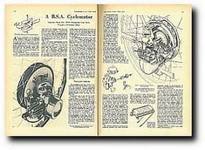
A 35cc cyclemotor, to be called the Winged Wheel, is to be marketed by BSA. Designed to replace the rear wheel of a normal bicycle, the unit embodies gear drive transmission through a three-plate clutch, a 9½in-diameter internal expanding brake and a heavy duty free-wheel of the locking roller type. Complete with control cables and levers, tyre and tube, fuel tank and fittings, the unit will retail at £25.
The two-stroke engine is incorporated in a 26 x 1¾in cycle wheel with the cylinder, horizontally disposed, in line with the cycle frame; the cylinder head faces forward into the air stream. Strengthened by heavy duty spokes, the wheel can be fitted to most types of standard bicycle. A separate fuel tank of half-gallon capacity is intended to be fitted in the carrier position above the rear wheel. Weight of the engine-wheel unit is given as just under 27 lb.
Enjoy more The Classic MotorCycle Magazine reading every month.
Click here to subscribe & save.
 Bore and stroke measurements of the engine are 36 x 34mm. The cylinder is machined from high-grade cast iron and is finned horizontally. At its top (or forward) end, the cylinder is spigoted to receive the light-alloy cylinder head, which has a hemispherical combustion space – and a centrally disposed boss for the long-reach sparking plug. Cylinder and head are secured to the crankcase, by four long studs and nuts and special saddle washers which bridge four pairs of adjacent head fins. Diametrically opposed inside the barrel, the outlet ends of the transfer ports are flared to impart a swirl to the compressed charge from the crankcase.
The carburettor is an Amal, fitted with an unusual strangler operated from the throttle lever. The aim, of course, is to keep the number of controls down to the minimum. This is achieved by employing a throttle lever fitted with a small ratchet which, when lifted, allows the lever to be moved past the position where the throttle is fully open. Movement of the lever beyond this point causes the blind end of a groove in the throttle slide to actuate a small tongue on the end of the pivoted strangler butterfly valve. Thus the valve is brought down to blank off the choke tube in order to provide the necessary rich mixture for cold starting.
 A low-expansion, silicon-aluminium alloy casting, the piston is of the slightly domed, deflectorless type and carries two pegged compression rings. The gudgeon-pin is fully floating, takes its bearing in a phosphor-bronze small-end bush and is retained by circlips. The big-end bearing consists of a single row of rollers which run between the crankpin and the hardened and ground big-end eye of the connecting rod. Material employed for the, connecting rod is case-hardened nickel-chrome steel with a tensile strength of 50 tons.
The mainshafts and their webs are of medium-carbon case-hardened steel and, with the crankpin, form a three-piece crankshaft assembly. Parallel ground, the crankpin is an interference fit in the webs. Supporting the crankshaft are two 1in outside-diameter roller bearings, one at each side.
Aluminium alloy is used for the crankcase castings. The inner, or right-hand, crankcase half is an integral part of a single, large casting which forms the shoe-plate of the brake as well as an enclosing shell to house the clutch and gear transmission mechanism. The outer, or left-hand, portion of the crankcase carries a roller journal bearing and a pressure oil seal, and it is extended to form a spigot on which the stator of a Series 90 WicoPacy mag-generator is mounted. The rotor, of course, is -carried on the left-hand side engine mainshaft. The Series 90 mag-generator is the latest version of the Bantamag and was fully described in The Motor Cycle for 11 September, 1952. For the Winged Wheel, the generator is fitted with a separate clothe cover, retained by a spring clip.
 The right-hand main-shaft is splined to carry a 17-tooth spur pinion which, situated in the transmission box, drives the clutch through a 66-tooth gear pinion on the clutch drum periphery. When the clutch is engaged, the drive is transmitted from a pinion on the clutch shaft to a fourth pinion in the gear train. This last pinion is riveted to the wheel hub, which is keyed to the large-diameter brake drum.
The clutch shaft is carried by two ball journal bearings, one at each end. One bearing is housed in the combined crankcase and brake cover plate (which houses also one of the main wheel bearings). The other bearing is housed in a secondary cover plate which closes that portion of the main shell in which the transmission is installed.
Ten small coil springs
Loading the clutch pressure plate are no fewer than ten small coil springs located in thimbles. The springs are manufactured in 18 swg. wire, are 7/16in diameter and have a 24 lb pressure rating. Cork inserts are used in the friction plates. A short clutch pushrod is actuated by a cable-operated bell-crank mounted on the outside of the transmission housing. The entire gear train runs in oil. Synthetic rubber oil seals are fitted on the dutch shaft and in the hub assembly as well as on the crankshaft.
Apart from its large diameter, the brake is unusual in that each shoe is mounted on a separate pivot. Operation is by means of a single, parallel cam. The shoes are linked by means of a single return spring situated close to the cam. In order to eliminate any possibility of chatter, each shoe has a locating screw which is inserted into the shoe plate and operates in a slot midway between the shoe pivot and the cam. Dimensions of the linings are 5¼in long x 5/8in wide. Brake operation is by cable from a handlebar lever.
 The silencer comprises a box-section expansion chamber and short discharge pipe. The unit is readily dismantled for cleaning purposes. Its lid is retained by one nut and, on its removal, the single baffle plate can be withdrawn.
Power developed by the wheel, it is stated, is sufficient to propel an ordinary cycle at a cruising speed of 20 mph; maximum speed is approximately 26 mph. Fuel consumption is expected to average around 200 mpg.
Last week a member of the staff of The Motor Cycle rode a bicycle fitted with a prototype model of the Winged Wheel. Starting with the engine either cold or warm was accomplished after a few easy turns of the pedals. The procedure was to pedal off with the clutch held out, and, with the throttle lever set at about one-third open, engage the clutch when a fast walking speed had been reached. The engine appeared to be quite happy, and two-stroked perfectly, at speeds in the region of 20 mph. Maximum speed achieved on level ground was 25 mph. At the lower end of the scale, the engine pulled extremely well. The large rear brake was most effective, and was endowed with sufficient sponginess to provide true delicacy of control. Power on hills was well sustained. After a baulk on average main-road gradients, the pedal assistance required was of a light nature. There was no vibration, and roughness was perceptible only when the engine was made to pull at inordinately low speeds. ![]() Download original article
Download original article