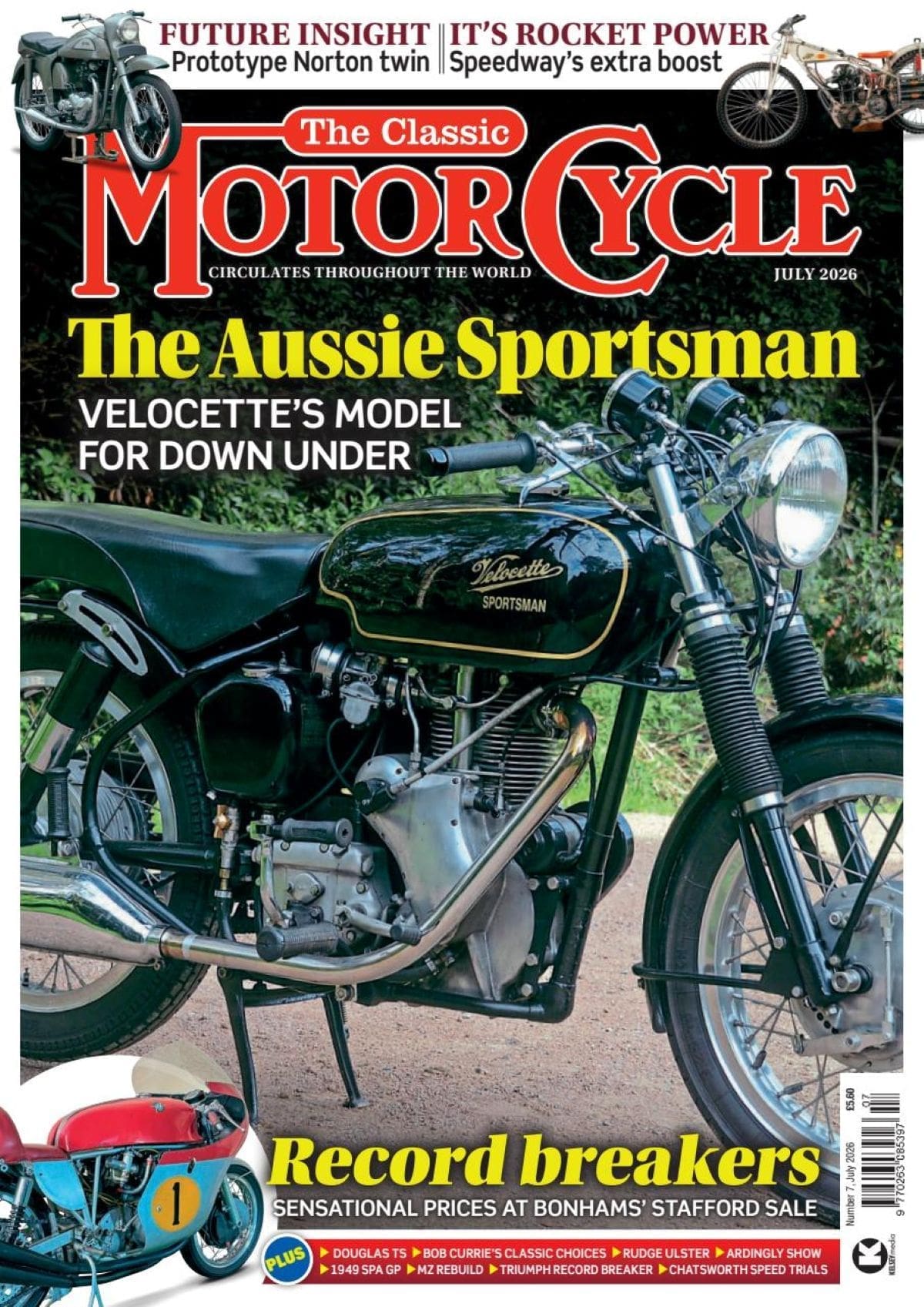
They’re ringing in the New Year at the BSA factory with a pair of brand-new big twins. Low-built and light (some 40 lb lighter than the current counterparts), the latest in the Small Heath line-up are packed with power and as compact in appearance as only unit-construction of engine and gear box can achieve.
Listed respectively as the A50 and A65 Stars, the two models are nominally a five-hundred and a six-fifty. But though the smaller mount is of 499 c.c., the larger has the unusual capacity of 654 c.c., which comes about through standardization of the stroke at 74mm. For the A50 the bore is 65.5mm, but the 75mm bore of the A65 endows it with slightly over-square characteristics.
Enjoy more The Classic MotorCycle Magazine reading every month.
Click here to subscribe & save.
In most other respects (save that an 8in diameter front brake and 7in diameter rear are featured on the 650 while the 500 has 7in brakes at front and rear) the specifications are identical.
 For the first time on any BSA twin there are alternating-current electrics. The rocker box is integral with the light-alloy cylinder head. The gear box—with an 'up for up, down for down' foot-change mechanism—has exceptionally wide pinion teeth. Detachable, pressed-steel panels enclose the oil tank, battery and carburettor and combine with the smooth, flowing Ines of the power unit in presenting a tidy overall aspect.
Compression ratio for each version is 7.5 to 1 and, while a power output of 28½ b.h.p. at 6,000 r.p.m. is claimed for the five-hundred, the larger model produces no less than 38 b.h.p. at 5,800 r.p.m.
Elimination of the older-style separate magneto and dynamo has helped to produce an attractive ‘power egg’ comprising two main light-alloy castings bolted together along the longitudinal centre line. The right-hand crankcase casting embraces the gearbox shell; the left-hand section forms also the inner half of the primary chaincase. Polished light-alloy covers at either side add a finishing touch.
In the main the engine design is completely fresh, though well-established BSA practice is followed in the disposition of the single, hollow camshaft at the rear of the cylinder block, and in the use of a manganese-steel forged crankshaft with bolted-on central flywheel and a tubular sludge trap located within the crank throw.
At the timing side the shaft is supported in a 1½in-diameter copper-lead bearing; on the drive side there is a ball journal bearing and outboard of it a garter-pattern oil seal. The end of the timing-side shaft carries a straight-tooth timing pinion and a skew gear which drives the duplex, gear-type oil pump.
 Mounted on the drive-side shaft is a triple-row driving sprocket, outboard of which is the rotor of the Lucas 60-watt RM19 alternator; the alternator stator is supported from the crankcase on three pillars and the electrical cables are directed through a gland in the crankcase.
Crankpin diameter is 1 11/16in, and the big-end bearings have steel-backed liners with micro-babbitt metalling. Connecting rods are in forged duralumin. Pistons are of orthodox, plain-skirt design and each is provided with three rings—a plain top ring, a taper-face second ring and a scraper ring.
Close-grain cast iron is employed for the cylinder block which, to ensure a rigid assembly, is deeply spigoted into the crankcase mouth. Operating in unbushed holes in the rear of the cylinder casting are the four tappets. They are unusually light to reduce reciprocating weight and have brazed-on, wear-resistant contact faces. Each tappet has a circlip at its upper end so that it cannot drop out when the cylinder block is raised.
The intermediate gear of the three which, in all, make up the timing train to the camshaft, serves to drive the twin contact-breaker assembly and auto-advance mechanism. A mechanical breather housed in the crankcase wall is operated by the left-hand end of the camshaft. Cam design features quietening ramps.
Pushrods are of solid duralumin with hardened-steel end cups, and they incline forward, between the cylinders, to operate the valves through rocker arms having a leverage ratio of 9 to 8 – a factor which reduces inertia loading. The light-alloy cylinder head (with part-spherical combustion chambers and cast-in valve seats) is a die-casting. Formed with the head is the rocker box and the three pillars supporting each rocker spindle.
 This integral construction offers a double advantage in that the rigid assembly resulting ensures a longer period between valve-clearance adjustment and, since the rocker cover carries no load, it is simpler to obtain an oil-tight joint. Inlet and exhaust valves are 1.41in and 1.31in in diameter respectively; the inlet valve has a hardened stem, the exhaust valve a brazed-on Stellite tip.
From the pump oil is delivered to the plain, timing-side main bearing, thence to the crankshaft and so to the big-end bearings; oil flung out from the bearings lubricates the pistons, small ends and camshaft. The rocker gear is fed separately from a bypass in the return pipe, with the union below the oil tank.
Primary drive is by a heavy-duty triplex chain of 3/8in pitch equipped with slipper tensioner, to a five-plate clutch. Ferodo friction material is bonded to the plates. The clutch drum, of cast iron, embodies shrouded driving slots; a vane-type shock absorber with rubber elements to smooth out the power impulses is incorporated in the clutch centre.
In relation to the overall dimensions of the 'housing, exceptionally wide gears for long life and quiet operation are employed in the four-speed gear box. Ball-bearings carry the mainshaft, while the layshaft runs on needle-roller bearings. In its essentials the gear-change mechanism is an enlarged version of that employed for the C15 and B40 single-cylinder models, in which the quadrant is integral with the transverse cam plate. Upward gear changes are made by raising the pedal; i.e., the operation is the reverse of that on other BSA twins.
Particular attention has been paid to ease of maintenance. Primary-chain adjustment comprises a hollow bolt projecting from the base of the chaincase with, at its upper end, a spigot, mounted button which bears against the underside of the tensioner slipper. A check can be made on chain tension by inserting a thin rod (such as a knitting needle) through the body of the adjusting bolt.
Similarly, on the face of the chaincase cover is a pear-shape cap which, when detached, reveals two inspection plugs. The forward plug gives access to the clutch-spring nuts, while removal of the rear plug exposes the clutch thrust-rod adjusting screw and locknut. On the right-hand side of the engine, a circular plate in the cover provides access to the contact-breaker assembly.
 To some extent the welded, tubular duplex frame is based on the current A-range design, but the wheelbase, at 54in, is about 2in shorter than before. There are differences also at the rear; the oil tank is mounted between the frame loops, and the rearward struts are omitted since the valanced rear mudguard is supported in cantilever fashion. Rear, suspension is by pivoted fork controlled by Girling hydraulically damped spring units with three-position adjustment for loading.
The fuel tank, of four gallons capacity, is insulated from the frame top tube by rubber and has a single-bolt fastening. Its sides are chromium-plated and each carries an elongated BSA Star Badge.
The oil tank, too, is rubber mounted, and though the tank is itself concealed by the right-hand, mid-section panel, the filler neck is exposed. The panels extend forward to encase the Amal carburettor (1in bore for the five-hundred, 1 1/8in for the six-fifty) and are located at the front on projections from the manifold lower studs and, at the rear, by a single Oddie fastener at each side. A carburettor float-chamber tickler lever projects forward of the left-hand panel.
Topping the hydraulically damped front fork is a 7in-diameter headlamp in a cylindrical nacelle. In the upper face of the nacelle is mounted the speedometer; to the right is the ammeter and, to the left, separate lighting and ignition switches. A neatly styled pressing embraces the fork top and extends rearward to shroud the handlebar clamps; a steering damper and steering-head lock are provided.
Wheels of 18in diameter (as compared with 19in formerly) have lowered the machine slightly. Tyre sections are 3.25in front and 3.50in rear, and the front tyre is of ribbed pattern. Floating shots, in full-width hubs, are employed on both brakes. As mentioned earlier, for the 499 c.c. model both brakes are 7in diameter, whereas the 654 c.c. model has 7in rear and 8in front brakes.
For the 499 c.c. A50 Star the standard finish is sapphire blue; the 654 c.c. A65 Star is normally finished in polychromatic green, but flamboyant, red may be obtained at extra cost. Alternatively, either machine can be supplied in black. ![]() View original article
View original article